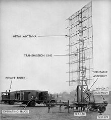

In telecommunications and radar, a reflective array antenna is a class of directive antennas in which multiple driven elements are mounted in front of a flat surface designed to reflect the radio waves in a desired direction. They are a type of array antenna. They are often used in the VHF and UHF frequency bands. VHF examples are generally large and resemble a highway billboard, so they are sometimes called billboard antennas. Other names are bedspring array[1] and bowtie array depending on the type of elements making up the antenna. The curtain array is a larger version used by shortwave radio broadcasting stations.
Reflective array antennas usually have a number of identical driven elements, fed in phase, in front of a flat, electrically large reflecting surface to produce a unidirectional beam of radio waves, increasing antenna gain and reducing radiation in unwanted directions. The larger the number of elements used, the higher the gain; the narrower the beam is and the smaller the sidelobes are. The individual elements are most commonly half wave dipoles, although they sometimes contain parasitic elements as well as driven elements. The reflector may be a metal sheet or more commonly a wire screen. A metal screen reflects radio waves as well as a solid metal sheet as long as the holes in the screen are smaller than about one-tenth of a wavelength, so screens are often used to reduce weight and wind loads on the antenna. They usually consist of a grill of parallel wires or rods, oriented parallel to the axis of the dipole elements.
The driven elements are fed by a network of transmission lines, which divide the power from the RF source equally between the elements. This often has the circuit geometry of a tree structure.
- ^ US Navy (September 1998). NAVEDTRA 14183 - Navy Electricity and Electronics Training Series. Vol. Module 11 - Microwave principles. Lulu Press. p. 236. ISBN 1-329-66770-0.
