Back Digital Flat Panel German Digital Flat Panel Italian DFP Japanese Digital Flat Panel Polish VESA Digital Flat Panel Russian
This article needs additional citations for verification. (March 2012) |
| Type | Digital video connector | ||
|---|---|---|---|
| Production history | |||
| Designer | Video Electronics Standards Association | ||
| Designed | February 14, 1999 | ||
| Superseded | VGA connector | ||
| Superseded by | Digital Visual Interface | ||
| General specifications | |||
| Pins | 20 | ||
| Data | |||
| Data signal | PanelLink protocol Transition Minimized Differential Signaling | ||
| Width | 3 bits plus clock | ||
| Max. devices | 1 | ||
| Protocol | PanelLink (Serial) | ||
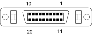
| Pinout | |||
 | |||
| Pin 1 | TMDS data 1 + | ||
| Pin 2 | TMDS data 1 – | ||
| Pin 3 | GND | ||
| Pin 4 | GND | ||
| Pin 5 | TMDS data C + | ||
| Pin 6 | TMDS data C – | ||
| Pin 7 | GND | ||
| Pin 8 | + 5V | ||
| Pin 9 | Reserved | ||
| Pin 10 | Reserved | ||
| Pin 11 | TMDS data 2 + | ||
| Pin 12 | TMDS data 2 – | ||
| Pin 13 | GND | ||
| Pin 14 | GND | ||
| Pin 15 | TMDS data 0 + | ||
| Pin 16 | TMDS data 0 – | ||
| Pin 17 | Reserved | ||
| Pin 18 | Reserved | ||
| Pin 19 | DDC data | ||
| Pin 20 | DDC clock | ||
The VESA Digital Flat Panel (DFP) interface standard specifies a video connector and digital TMDS signaling for flat-panel displays.[1] It features 20 pins and uses the PanelLink protocol; the standard is based on the preceding VESA Plug and Display (P&D) standard, ratified in 1997. Unlike the later, electrically-compatible Digital Visual Interface (DVI, 1999), DFP never achieved widespread implementation.
- ^ Manchester, Gary (1999). The VESA Digital Flat Panel (DFP) Standard: A White Paper (PDF) (Report). VESA Marketing Committee. Archived from the original (PDF) on January 12, 2016.